 English
 中文简体
中文简体 русский
 Español
 Français
What defines thin wall injection moulding
How does it differ from conventional injection moulding?
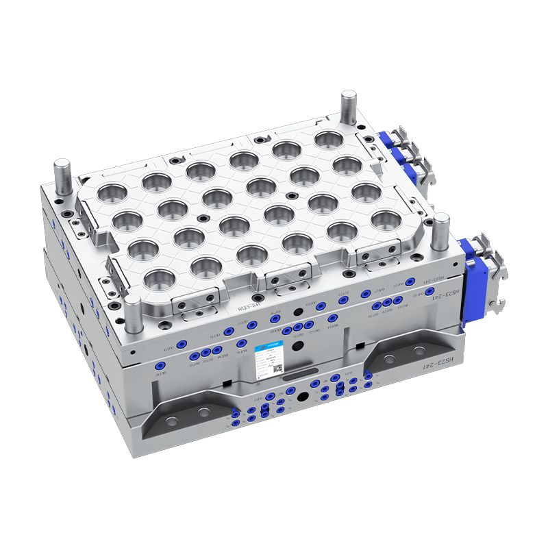
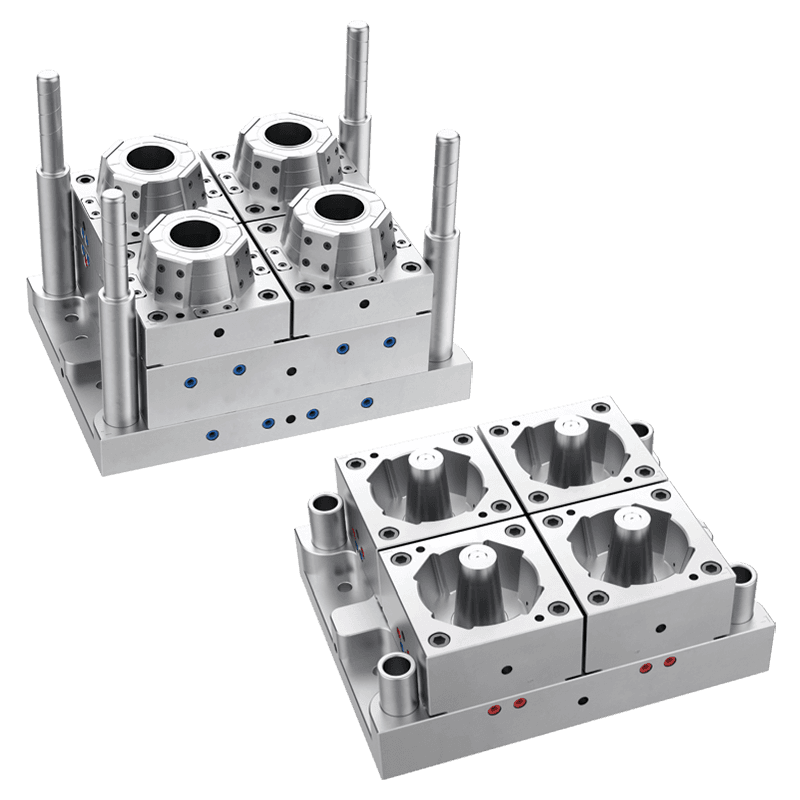
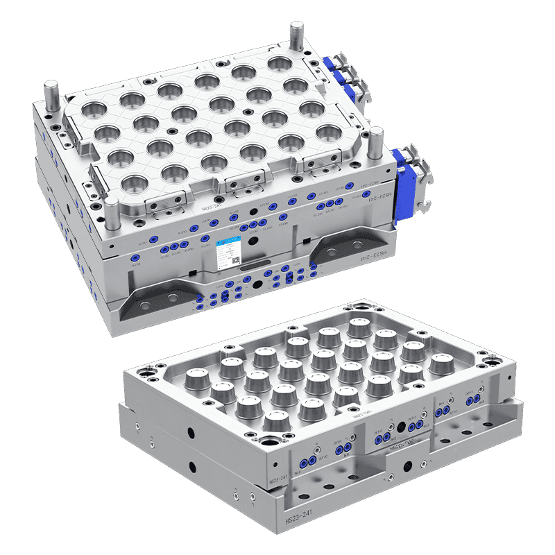
Thin-wall injection moulding refers to the production of plastic parts with wall thicknesses significantly below those of conventional moulding. While there is no universal industry standard, parts with wall thicknesses of 1.0 millimeter or less are generally considered thin wall, with some applications—such as food containers and caps—reaching 0.3 to 0.6 millimeters. Conventional injection moulding typically produces parts with wall thicknesses of 2.0 to 4.0 millimeters.
The primary difference between thin-wall and conventional moulding lies in the relationship between flow length and wall thickness. In conventional moulding, the flow length (the distance molten plastic travels from the gate to the farthest point of the cavity) divided by wall thickness is typically 50:1 to 100:1. In thin-wall moulding, this ratio often exceeds 150:1 and can reach 300:1 or more. This high ratio means the molten plastic must travel long distances through very narrow passages before the cavity fills, creating challenges not present in conventional moulding.
Cooling behavior also differs substantially. Thin-wall parts have a high surface-area-to-volume ratio, meaning they lose heat rapidly. While this allows for shorter cooling times—often 2 to 5 seconds compared to 10 to 30 seconds for conventional parts—it also requires that the mould cavity fill completely before the material solidifies. Injection speeds in thin wall moulding are typically 300 to 1,000 millimeters per second, compared to 50 to 150 millimeters per second for conventional moulding. Injection pressures reach 1,500 to 2,500 bar (22,000 to 36,000 psi), significantly higher than the 500 to 1,500 bar typical for conventional processes.
What materials are suitable for thin wall injection moulding, and what properties make them appropriate?
Material selection is critical to successful thin wall moulding. The polymer must flow easily through narrow cavities, solidify rapidly, and still produce a part with adequate strength for its intended application. Not all thermoplastics are suitable; those with high melt flow rates (MFR) are preferred.
Polypropylene (PP) is the most widely used material for thin wall moulding, particularly for food containers, caps, and closures. High-flow grades of PP have MFR values of 30 to 100 grams per 10 minutes (tested at 230°C/2.16 kg), compared to standard grades with MFR of 5 to 15. These high-flow grades contain additives such as peroxide-controlled rheology modifiers that reduce molecular weight and narrow molecular weight distribution. The result is lower melt viscosity, allowing the material to fill thin cavities without excessive injection pressure. PP also exhibits semi-crystalline behavior, allowing rapid solidification and short cycle times.
Polystyrene (PS) is another common material, especially for disposable cups, lids, and cutlery. General-purpose polystyrene (GPPS) and high-impact polystyrene (HIPS) are used. PS has lower shrinkage than PP (0.4 to 0.7 percent versus 1.2 to 2.0 percent), which simplifies mould design and dimensional control. However, PS is more brittle than PP and has lower heat resistance.
Polyethylene (PE) , particularly high-density polyethylene (HDPE), is used for thin wall containers requiring chemical resistance or flexibility. HDPE grades with MFR of 20 to 50 are common. PE has slower crystallization than PP, which may extend cycle times, but offers good impact resistance and environmental stress crack resistance.
Polyethylene terephthalate (PET) is used for thin wall containers where clarity and barrier properties are required. PET requires drying before processing (moisture content below 0.02 percent) and has a narrower processing window than PP or PS. However, PET provides excellent transparency, good mechanical strength, and is widely recyclable.
What are the common defects in thin wall moulding, and how can they be prevented?
Thin wall moulding presents unique defect challenges due to high injection speeds, extreme flow ratios, and rapid cooling. Understanding these defects and their root causes is essential for achieving acceptable part quality.
Short shots (incomplete filling)
Short shots occur when the molten plastic does not reach all areas of the cavity before solidification. Causes include insufficient injection speed or pressure, inadequate melt temperature, or venting issues. Prevention strategies include increasing injection speed (up to 800–1,000 mm/s), raising melt temperature (within material limits), and adding vents (0.01–0.03 mm depth) at the last points to fill. Simulation software can identify flow path issues before mould construction.
Sink marks
Sink marks are depressions on the part surface caused by localized shrinkage in thicker sections. In thin wall moulding, sink marks typically occur at rib intersections, bosses, or gate areas where material accumulates. Prevention involves redesigning ribs and bosses to maintain uniform wall thickness (rib thickness should be 40 to 60 percent of adjacent wall thickness), reducing packing pressure, and optimizing gate location to minimize flow distances.
Warpage
Thin wall parts are prone to warpage due to orientation of polymer molecules and differential cooling across the part. As material flows through the narrow cavity, molecules become aligned in the flow direction, causing anisotropic shrinkage—the part shrinks differently in the flow direction versus the cross-flow direction. Prevention strategies include: designing parts with symmetrical geometries where possible; placing gates at the part center to create balanced flow; using multi-gate designs to reduce flow distances; and optimizing cooling channel layout for uniform temperature distribution.
Flash
Flash is excess material that escapes from the cavity at the parting line or around ejector pins. In thin wall moulding, high injection pressures (1,500–2,500 bar) increase the risk of flash. Causes include insufficient clamp force, mould deflection, or damaged parting line surfaces. Prevention involves verifying that the moulding machine has adequate clamp capacity, using support pillars behind the cavity to prevent mould deflection, and maintaining clean parting line surfaces.
Burn marks
Burn marks appear as black or brown discoloration on the part surface. They occur when trapped air is compressed and heated to the point of igniting or degrading the plastic. In thin wall moulding, the high-speed injection leaves little time for air to escape through vents. Prevention includes adding sufficient venting (0.01–0.03 mm depth) along the parting line, using vacuum assistance to remove air from the cavity before injection, and reducing injection speed in the final 5 to 10 percent of fill.
Flow marks and surface defects
Flow marks (visible flow lines, tiger stripes, or gate blush) are common in thin wall moulding due to the extreme shear rates near the gate. Prevention strategies include: increasing melt temperature to reduce viscosity; optimizing gate design (larger gates, fan gates, or multiple gates); and using injection speed profiling—slow initial fill to reduce gate shear, then fast fill for the remainder of the cavity.
Contact Us
Email: [email protected]; Or fill out the contact form below.
Yongkang Huashun Mould Co., Ltd. is a technology-based enterprise specializing in the production of thin-walled injection molds.
PRODUCT
- Disposable Plastic Round Food Container Moulds
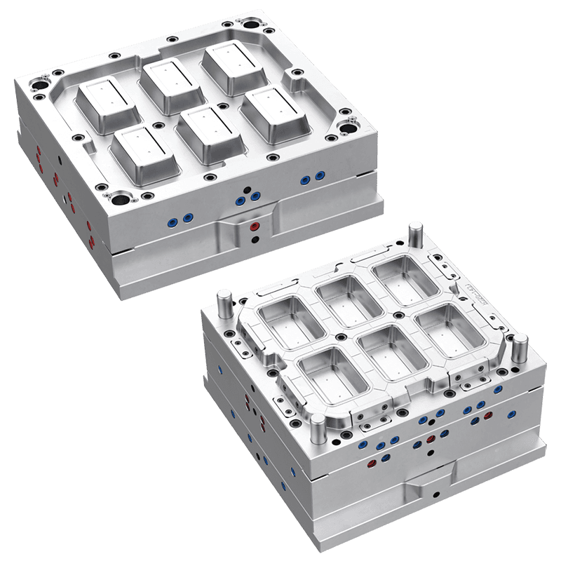
- Disposable Plastic Square Food Container Moulds
- Disposable Bubble Tea Plastic PP Cup Mould Series
- Disposable Plastic Knife Fork And Spoon Mould Series
- Disposable Plastic Multi-grid Food Container Mould Series
- Disposable Plastic Portion Cup Mould Series
- Disposable Plastic Cup Mould Series
